Hi everyone,
I’ve been working at a mid-sized hospital for about a year now, and even though I mainly take care of the infrastructure and security side, every now and again, I need to change I-SIDs or VLANs on some of our switches.
We currently have a little more than 100 switches, and all of them are from Extreme Networks. Fabric Connect is not really implemented yet, but hopefully, it will be within the next couple of years. But that’s not the actual point of this post, since I am not going to implement it. I want to understand the switches a bit more. Unfortunately, I find the amount of information concerning the Fabric Connect configuration a bit lacking. So, that’s why I decided to gather as much as possible and try it out myself.
The cool thing about Fabric Connect is that it (technically) simplifies the switch configuration tremendously. Once everything is set up, we have something similar to a Layer 3 based network and only have to configure the edge ports. There is no need to configure every single uplink port for a new VLAN. Just create the VLAN at the edge switches and ports you want and the Fabric will take care of the rest.
It’s similar to VXLAN, which basically everyone else uses, but this setup seems way simpler.
To make sure that I don’t break anything in our productive environment, I will be setting this up in GNS3 and using the Extreme Networks Virtual VOSS VM. What we have to keep in mind is that the VMs do not actually have the data plane implemented. So we won’t have any traffic when using Fabric Connect. This means we cannot fully test the setup. But ISIS and a few other things work fine. This should give me enough to verify the configuration. Hopefully.
This will be as much a learning experience for me as it might hopefully help you, or at least be interesting.
For this, I will assume that you have GNS3 running. You can get the VOSS image from this GitHub link. I will be using “VOSS 9.3.0” for this.
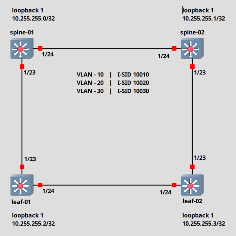
This will be the topology.
Let’s begin.
Switch configuration cleanup (Optional)
First we will start with a cleanup. These switches boot with a preconfigured SPBM/ISIS configuration, which means that technically we don’t have to do anything at all. It works out of the box. But I want to modify the defaults and set this up myself.
We will do these steps on every switch.
To Login, use rwa / rwa for the username and password. We have to change the password after the first login.
Login: rwaPassword: ***Enter the New password : ********Re-enter the New password : ********Password changed successfully5520-24T-FabricEngine:1>
To get into the configuration mode, we have to first enter the commands “enable” then “configure terminal”. Keep in mind that you can shorten every command, as long as it’s unique. For example, you can just type “ena” and hit enter. It will still work.
# Switch into privilege mode5520-24T-FabricEngine:1> enable# Switch into configuration mode5520-24T-FabricEngine:1# configure terminal5520-24T-FabricEngine:1(config)#
The first step, will be to disable screen logging. It gets annoying very fast.
# Disable logging display in the terminal5520-24T-FabricEngine:1(config)# no logging screen
Next, we set the prompt name.
# Change prompt5520-24T-FabricEngine:1(config)# prompt spine-01spine-01(config)#
Alright. Let’s actually start configuring.
We will remove the spbm and ISIS configuration.
# Remove the preconfigured SPBM/ISIS configurationspine-01(config)# mgmt vlanspine-01(config)# no enablespine-01(config)# mgmt oobspine-01(config)# no enablespine-01(config)# exitspine-01(config)# no auto-sense onboarding i-sidspine-01(config)# no router isis enablespine-01(config)# no spbmspine-01(config)# no i-sid name 15999999spine-01(config)# no vlan i-sid 4048spine-01(config)# vlan delete 4048
SPBM configuration (Script)
Ok, now we can create our SPBM configuration. In this part, we will create this using the script provided by the switch.
Everything in red was changed by me.
spine-01(config)# run spbm************************************************************* This script will guide you through configuring the ****** Extreme Networks switch for optimal operation of SPB. ****** Extreme Networks switch for optimal operation of SPB. ****** ---------------------------------------------------****** The values in [] are the default values, you can ****** input alternative values at any of the prompts. ****** If you wish to terminate or exit this script ****** enter ^C <control-C> at any prompt. ****** NOTE: THE COMMAND WILL TEMPORARILY FLAP IS-IS,SPBM *************************************************************SPB Ethertype <0x8100,0x88a8> [0x8100]:SPBM instance <1-100> [1]:SPB primary BVLAN <2-4059> [4051]:SPB secondary BVLAN <2-4059> [4052]:ISIS system id <xxxx.xxxx.xxxx> [0c84.98f7.0084]:0001.0000.0001SPB nickname <x.xx.xx> [7.00.84]:1.00.01SPB Manual Area <xx.xxxx.xxxx...xxxx> [49.0000]:ISIS System Name [spine-01]:Enable SPBM multicast (y/n) [n]:Enable IP shortcuts (y/n) [n]:yLoopback interface ID <1-256> [1]:Loopback interface IP and subnet <a.b.c.d/x>:10.255.255.0/32Configure SPBM SMLT? (y/n) [n]: ISIS port interfaces <a/b,c/d>[]:1/23,1/24ISIS MLT interface <MLT ID LIST> []:Enable CFM SPBM (y/n) [n]:yEnter CFM SPBM MEPID <1-8191> [1]:Enter CFM SPBM level <0-7> [4]:****CONFIGURATION IN PROGRESS****
Do this for all switches and just modify the “system ID”, the “SPB nichname”, the “CFM SPBM MEPID” and the “loopback IP”.
Make sure that the “CFM SPBM MEPID” is unique on every switch. This is used for fault monitoring purposes.
For example. For the spine-02 I used the following data.
ISIS system id <xxxx.xxxx.xxxx> [0c84.98f7.0084]:0002.0000.0002SPB nickname <x.xx.xx> [7.00.84]:1.00.02Loopback interface IP and subnet <a.b.c.d/x>:10.255.255.1/32Enter CFM SPBM MEPID <1-8191> [1]: 2
Check the SPBM/ISIS configuration
That’s basically it, actually. Let’s check a few things.
The ISIS adjacency.
spine-01(config)# show isis adjacencies================================================================================================================================== ISIS Adjacencies==================================================================================================================================INTERFACE L STATE UPTIME PRI HOLDTIME SYSID HOST-NAME STATUS AREA AREA-NAME ----------------------------------------------------------------------------------------------------------------------------------Port1/23 1 UP 00:00:17 127 24 0003.0000.0003 leaf-01 ACTIVE HOME Port1/24 1 UP 00:00:22 127 26 0002.0000.0002 spine-02 ACTIVE HOME ----------------------------------------------------------------------------------------------------------------------------------Home: 2 out of 2 interfaces have formed an adjacencyRemote: 0 out of 0 interfaces have formed an adjacency----------------------------------------------------------------------------------------------------------------------------------
We can see that the switches found each other. Let’s check the same on the leaf-02 switch.
leaf-02(config)# show isis adjacencies================================================================================================================================= ISIS Adjacencies==================================================================================================================================INTERFACE L STATE UPTIME PRI HOLDTIME SYSID HOST-NAME STATUS AREA AREA-NAME ----------------------------------------------------------------------------------------------------------------------------------Port1/23 1 UP 00:01:41 127 23 0002.0000.0002 spine-02 ACTIVE HOME Port1/24 1 UP 00:01:45 127 21 0003.0000.0003 leaf-01 ACTIVE HOME
Create VLAN and I-SID
Alright. Before we check a few more things, let’s create our VLANs and associate those with the I-SIDs. Do this on every switch.
## Create the VLANs 10,20,30spine-01(config)# vlan create 10 type port-mstprstp 0spine-01(config)# vlan create 20 type port-mstprstp 0spine-01(config)# vlan create 30 type port-mstprstp 0## Check if the VLAN was createdspine-01(config)# show vlan name==================================================================================================== Vlan Name====================================================================================================VLAN IF ID INDEX NAME -----------------------------------------------------------------------------------------------------------1 2049 Default 10 2058 VLAN-10 20 2068 VLAN-20 30 2078 VLAN-30 4051 6099 VLAN-4051 4052 6100 VLAN-4052
Next, we create the I-SIDs.
## Create the I-SIDsspine-01(config)# i-sid 10010spine-01(config)# i-sid 10020spine-01(config)# i-sid 10030
Assign the VLAN to the I-SID.
## Associate the I-SID with the VLANspine-01(config)# vlan i-sid 10 10010spine-01(config)# vlan i-sid 20 10020spine-01(config)# vlan i-sid 30 10030
Let’s check our configuration.
spine-01(config)# show vlan i-sid==================================================================================================== Vlan I-SID====================================================================================================VLAN_ID I-SID VLAN NAME I-SID NAME -----------------------------------------------------------------------------------------------------------1 10 10010 VLAN-10 ISID-10010 20 10020 VLAN-20 ISID-10020 30 10030 VLAN-30 ISID-10030 4051 4052
Now we can check the I-SID discovery in the Fabric.
Here we can see, that the switch discovered the ISID areas from the other switches.
spine-01(config)# show isis spbm i-sid all=============================================================================================================== SPBM ISID INFO==============================================================================================================ISID SOURCE NAME VLAN SYSID TYPE HOST_NAME ISID NAME AREA AREA NAME--------------------------------------------------------------------------------------------------------------10010 1.00.01 4052 0001.0000.0001 config spine-01 ISID-10010 HOME 10020 1.00.01 4052 0001.0000.0001 config spine-01 ISID-10020 HOME 10030 1.00.01 4052 0001.0000.0001 config spine-01 ISID-10030 HOME 10010 1.00.02 4052 0002.0000.0002 discover spine-02 ISID-10010 HOME 10020 1.00.02 4052 0002.0000.0002 discover spine-02 ISID-10020 HOME 10030 1.00.02 4052 0002.0000.0002 discover spine-02 ISID-10030 HOME 10010 1.00.03 4052 0003.0000.0003 discover leaf-01 ISID-10010 HOME 10020 1.00.03 4052 0003.0000.0003 discover leaf-01 ISID-10020 HOME 10030 1.00.03 4052 0003.0000.0003 discover leaf-01 ISID-10030 HOME 10010 1.00.04 4052 0004.0000.0004 discover leaf-02 ISID-10010 HOME 10020 1.00.04 4052 0004.0000.0004 discover leaf-02 ISID-10020 HOME 10030 1.00.04 4052 0004.0000.0004 discover leaf-02 ISID-10030 HOME --------------------------------------------------------------------------------------------------------------Home: Total number of SPBM ISID entries configured: 3--------------------------------------------------------------------------------------------------------------Home: Total number of SPBM ISID entries discovered: 9Remote: Total number of SPBM ISID entries discovered: 0--------------------------------------------------------------------------------------------------------------Home: Total number of SPBM ISID entries: 12Remote: Total number of SPBM ISID entries: 0--------------------------------------------------------------------------------------------------------------
Assign Port to I-SID
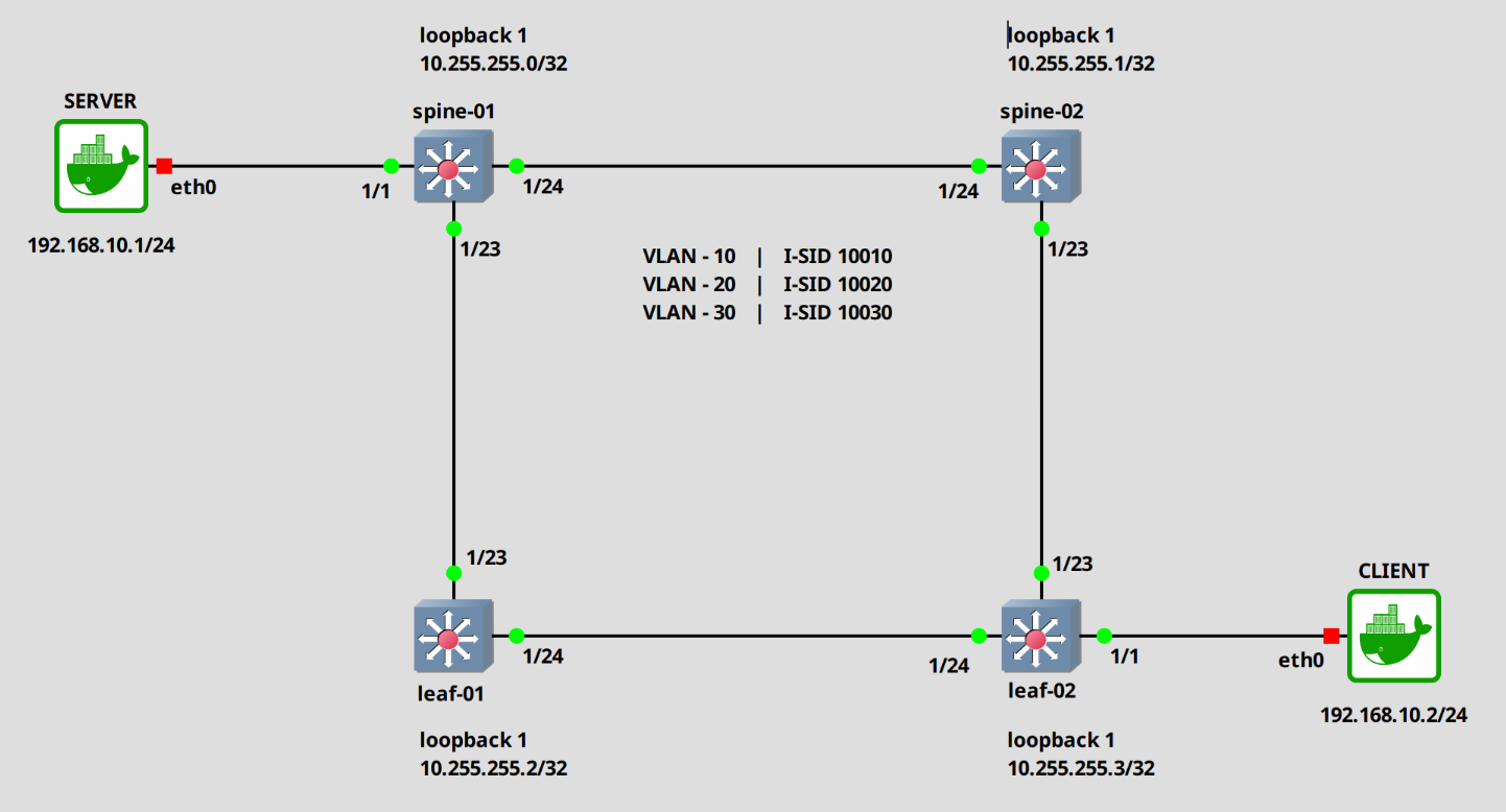
We will expand out network with two additional systems. A server and a client. The server will be attached to Port 1/1 on spine-01 and the client on port 1/1 on the lead-01 switch.
Alright. Let’s assign the ports to the I-SID 10010. In this example, I will configure them as untagged. Do the same on the “leaf-02” switch.
### Spine-01## First disable auto-sense and enable flex-unispine-01(config)# interface gigabitEthernet 1/1spine-01(config)# no auto-sense enablespine-01(config)# flex-uni enable## Setup the i-sidspine-01(config)# i-sid 10010spine-01(elan:10010)# untagged-traffic port 1/1
### Leaf-02## First disable auto-sense and enable flex-unileaf-02(config)# interface gigabitEthernet 1/1leaf-02(config)# no auto-sense enableleaf-02(config)# flex-uni enable## Setup the i-sidleaf-02(config)# i-sid 10010leaf-02(elan:10010)# untagged-traffic port 1/1
Check the configuration.
spine-01(config)# show i-sid============================================================================================================== Isid Info==============================================================================================================ISID ISID PORT MLT ORIGIN ISID ID TYPE VLANID INTERFACES INTERFACES NAME --------------------------------------------------------------------------------------------------------------10010 ELAN 10 u:1/1 - C --- - --- - - -- ISID-10010 10020 ELAN 20 - - C --- - --- - - -- ISID-10020 10030 ELAN 30 - - C --- - --- - - -- ISID-10030 16777001 ELAN N/A - - C --- - --- - - -- FAN-ISID
Now, normally, if I am correct, the systems should be able to ping each other. But, like I said in the beginning, the data plane is not fully implemented in the virtual VOSS VMs. So Fabric traffic is not forwarded.
What we can see though, is that the loopback IPs can ping each other.
## pinging leaf-02spine-01(config)# ping 10.255.255.3Sending ping in context grt 10.255.255.3 is alive
We are technically done, but I want to show a few more things before I finish.
First, how to transport tagged traffic.
Assign c-vid to ports (tagged traffic)
There are multiple ways, but this seems to be the preferred one.
## Disable auto-sense and enable flex-unispine-01(config)# interface gigabitEthernet 1/2spine-01(config)# no auto-sense enablespine-01(config)# flex-uni enable## configure the customer vidspine-01(config)# i-sid 10010spine-01(elan:10010)# c-vid 10 port 1/2spine-01(config)# i-sid 10020spine-01(elan:10020)# c-vid 20 port 1/2spine-01(config)# i-sid 10030spine-01(elan:10030)# c-vid 30 port 1/2
Check the configuration.
spine-01(config)# show i-sid================================================================================================================================== Isid Info==================================================================================================================================ISID ISID PORT MLT ORIGIN ISID ID TYPE VLANID INTERFACES INTERFACES NAME ----------------------------------------------------------------------------------------------------------------------------------10010 ELAN 10 c10:1/2 - C --- - --- - - -- ISID-10010 u:1/1 - 10020 ELAN 20 c20:1/2 - C --- - --- - - -- ISID-10020 10030 ELAN 30 c30:1/2 - C --- - --- - - -- ISID-10030 16777001 ELAN N/A - - C --- - --- - - -- FAN-ISID c: customer vid u: untagged-traffic
We can combine the untagged and tagged configuration.
spine-01(config)# i-sid 10010spine-01(elan:10010)# untagged-taffic port 1/3spine-01(config)# i-sid 10020spine-01(elan:10020)# c-vid 20 port 1/3
Let’s check the configuration.
spine-01(config)# show i-sid10010 ELAN 10 c10:1/2 - C --- - --- - - -- ISID-10010 u:1/1,1/3 - 10020 ELAN 20 c20:1/2,1/3 - C --- - --- - - -- ISID-10020 10030 ELAN 30 c30:1/2 - C --- - --- - - -- ISID-10030 16777001 ELAN N/A - - C --- - --- - - -- FAN-ISID c: customer vid u: untagged-traffic
Assign VLAN directly without I-SID
## configure port 1/5spine-01(config)# interface gigabitEthernet 1/5spine-01(config-if)# no auto-sense enablespine-01(config-if)# encapsulation dot1qspine-01(config-if)# default-vlan-id 10spine-01(config-if)# vlan member add 20 1/5spine-01(config-if)# vlan member add 30 1/5
Check the configuration.
spine-01(config)# show interface gigabitEthernet vlan 1/5==================================================================================================== Port Vlans====================================================================================================PORT DISCARD DISCARD DEFAULT VLAN PORT UNTAG DYNAMIC UNTAG FA/ NUM TAGGING TAGFRAM UNTAGFRAM VLANID IDS TYPE DEFVLAN VLANS VLANS Flex UNI-----------------------------------------------------------------------------------------------------------1/5 enable false false 10 10,20 normal disable P disable ----------------------------------------------------------------------------------------------------
And that is it.
I will go through a few more configurations in another post, but this should to it for now.
Hope this is somewhat useful.
Till next time.
Kommentare